Why grounding?
Earthing the installation allows the fault current to flow to the ground in the event of an insulation fault. It also ensures discharge of the fault current due to lightning strikes and electromagnetic disturbances.
This earthing will thus ensure:
- The protection of people and their safety
- Protection of property and facilities
What are the elements that make up the earth circuit:
The earth circuit is made up of several elements. They will be in contact with the ground and will diffuse the fault current and the measurement:
- The electrode or earth rod.
- The visit look
- Earth conductor connections
- Earth conductors or earth cables
- The cut-off bar
The resistivity of the ground is very important in the final choice of the elements that make up the earth circuit, in fact the grounds are more or less conductive and their resistivity depends on:
- The nature of the terrain (marshy soil, rock, gravel, sand, etc.)
- Water content (Moisture)
- Climatic variations
The resistivity of the ground is expressed in Ohmmeter and can vary between 10 Ω.m and 10,000 Ω.m, it will depend on the above factors.
Ground resistivity depending on the nature of the ground:
|
Nature of the land |
Resistivity in Ωm |
|
swampy land |
1 to 30 |
|
silt |
20 to 100 |
|
humus |
10 to 150 |
|
wet peat |
5 to 100 |
|
plastic clay |
50 |
|
marls and compact clays |
100 to 200 |
|
Jurassic marls |
30 to 40 |
|
clay sands |
50 to 500 |
|
siliceous sands |
200 to 300 |
|
bare stony ground |
1,500 to 3,000 |
|
stony ground covered with grass |
300 to 500 |
|
soft limestones |
100 to 300 |
|
compact limestones |
1,000 to 5,000 |
|
cracked limestones |
500 to 1000 |
|
shale |
50 to 300 |
|
granite and sandstone |
1,500 to 10,000 |
|
very weathered granite and sandstone |
100 to 600 |
Resistivity (Ωm) of different terrains (according to NF C 15-100)
Earth measurement by the 62% method
Before the measurement, the cut-off strip must be disconnected in order to isolate the earth electrode from the rest of the installation, thus allowing the earth resistance to be measured periodically.
To carry out the measurement it will be necessary to use a measuring device called Tellurometer.
This method requires the use of 3 stakes. It consists in injecting a current between a first electrode and the earth rod of the installation (or the rod connected to the loop at the bottom of the excavation), the third rod will allow the measurement of the voltage.
To implement this method it is necessary to start from the stake connected to the excavation bottom P1 and place a second stake P2 at more than 10m the third stake P3 will be placed at 62% of the distance (L1) between P1 and P2 this allows ” be outside the zones of influence created by the flow of current. (See diagram below).
If the measurement is not conclusive, it will be necessary to lengthen the earth rod connected to the excavation bottom loop or add one or more earth rods in order to obtain a value less than 100 Ohms.
If the measurement is less than 100 Ohms it will have to be validated by moving P3 to 52% and 72% of P2, if the measurement does not vary, the positioning of P1 can be validated. (See diagram below)
The best solution for creating an earth electrode is the bottom digging loop.
The belt or buckle at the bottom of the excavation is recommended for new constructions.
This solution consists in making a loop with a bare copper or an earth cable around the building figure 4. Bare copper will be placed under the clean concrete or buried 1m below the foundations of the exterior walls. Bare copper must be in direct contact with the ground.
For existing buildings, the bottom conductor must be buried all around the exterior walls of the premises to a depth of at least 1 meter.
Material required to make the earth connection:
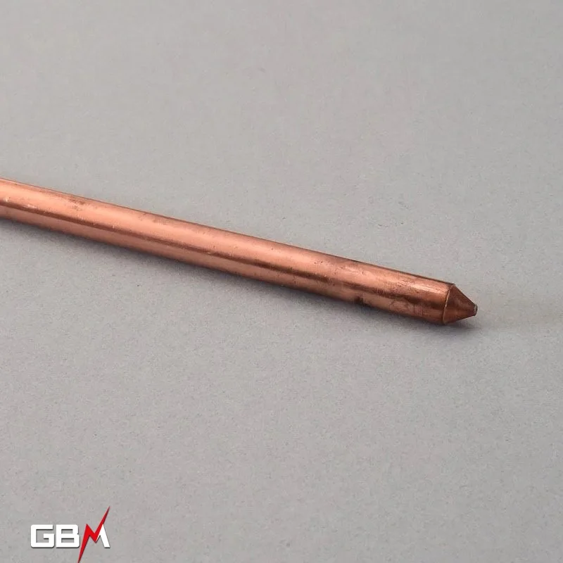
Electrode or earth rod
Once the earth rod is driven into the ground it will ensure the discharge of the fault current, the rods are made of copper-coated steel their copper covering offers better conductivity than galvanized steel rods.
Ref: P5010 / P5015 / P5020
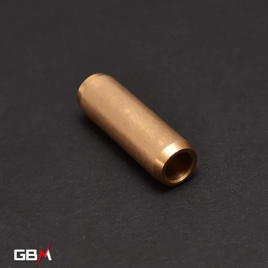
Coupling sleeve
The coupling sleeve will make it possible to assemble several earth rods in order to increase their length and provide a better contact surface and thus obtain the desired Ohmic value.
Ref: MAC14
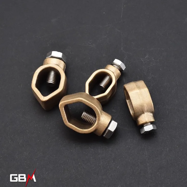
Lugs for earth rod
They provide a mechanical connection between the cable or strip and the earth rod, the products in contact being all at the same potentials, there will be no galvanic corrosion phenomenon.
Ref: CPC1670 / CPC2595 / CPC30
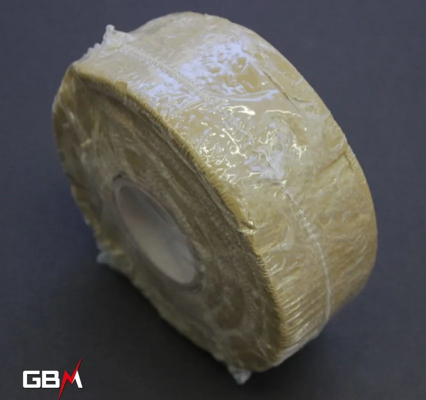
Corrosion protection strip
It is used to isolate the various mechanical connections present on the earth circuit and thus prevent any corrosion.
Ref: BPCORRO
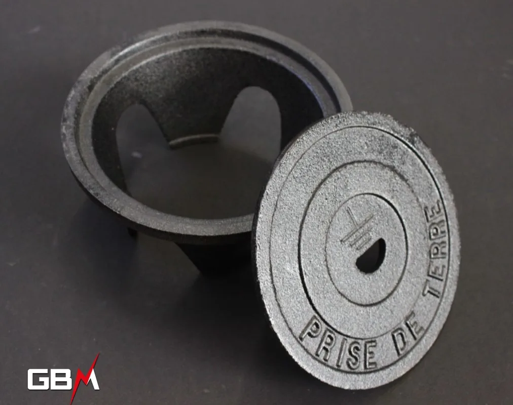
Inspection look
It allows easy access to the earth rod and its connection to the bare copper will allow measurements to be taken and the durability of the installation to be checked.
Ref: RV180
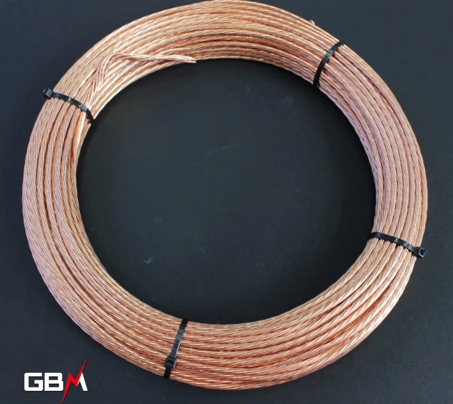
Earth wire or bare copper
The copper cable will allow the diffusion of the fault current towards the electrode or the earth rod.
Ref: CNR16 /…
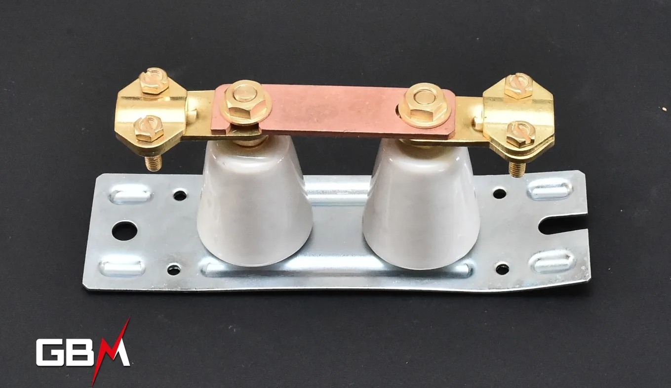
The cut-off bar
It is located between the earth stake and the electricity meter. Its role is to split the circuit into 2 parts, the upstream part (from the meter to the socket circuits, lighting, etc.) and the downstream part to the earth circuit. When separating the circuit this will allow you to measure the resistance of the earth electrode. This must be less than 100 Ohm.
Ref: BC1635 / BC1670

Last important points
Water, heating, or gas pipes must absolutely not be used as an earth connection.
Examples of implementation


We remain at your disposal for any technical or commercial supplement.

")