Electromagnetic compatibility (EMC)
Electromagnetic compatibility is the ability of a device
electrical system to function in an acceptable manner in its electromagnetic environment without itself disturbing the electrical installations close to it. We speak of “good neighborhood
electromagnetic ”. Electromagnetic compatibility and its methods make it possible to avoid disturbances, ie when there is coupling between a source device (parasitic signal) and a victim device (vulnerable to the parasitic signal).
These methods become more and more useful with increasing
constant number of low current electronic systems on the one hand and an ever increasing energy demand. This context
electric mixes systems that are very di ff erent in terms of their intensities, voltages and frequencies. There are a multitude of possible disruptions and they must be avoided. For this GBM France offers you some explanations and solutions.
Equipotentiality
Equipotentiality is an important principle for the sustainability of electrical systems. Very common for individual systems, equipotentiality is more di ffi cult to set up for complex electrical installations, made up of a multitude of devices with di ff erent properties (direct / alternating current, high frequency / low frequency, etc.)
However, it is essential for systems with low intensity currents which carry information (automation, measurement system, etc.) or in areas sensitive to electrical disturbances. For example, AtEx (explosive atmosphere) zones are sensitive to electrical disturbances which can be of sufficient energy to activate gas or dust explosions.
A benchmark of potential
Equipotentiality is defined as a potential reference for several electrical devices. This reference is however di ff erent from the “land”, necessary
technological and human security.
Within the framework of EMC there is therefore a potential reference between all
metallic elements of the installation, including those that are inaccessible and included in the structure (frame, beam, etc.). All the equipment is therefore connected and has the same reference potential.
Linear inductance
We wonder what factors are to be taken into account when linking all these
metal equipment. Inductance is one of them, through the properties of the links between these devices. It is about the phenomenon which connects to any electric current propagating in a medium an induced magnetic field. These magnetic fields can be very problematic for many electrical systems. So we tend
to reduce the inductance of the installation as much as possible.
To understand how the magnetic fields created by the electrical installation will evolve, we will look at the concept of impedance. We denote by Z the impedance of a component (here impedance of the inductance), and we can see it as the analogy in alternating current of a resistance in direct current. In addition, this impedance will be dependent on the frequency of the alternating current (how many times the current changes sign in 1 second). We know that Z = 2πfL (f the frequency (Hz), L the inductance (henry)), so that Z increases if the frequency f increases. At high frequency the impedance can therefore be very high. A low inductance (L) is therefore required. Fortunately there are materials with low linear inductance, such as short but wide mass braids. Thus, to reduce the impedance of the system, links (between the electrical equipment) of low linear inductance, such as ground braids or strips, are chosen instead.
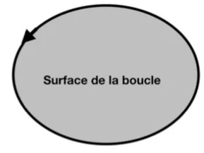
In addition it should be noted that in addition to the distance at which the
electrical equipment (short but wide connections), do not create loops or loves, which greatly increases the linear inductance and therefore the magnetic field created. The loop would behave similar to a coil.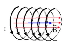
There are two more last phenomena to take into account when setting up
equipotentiality. We speak of inductive coupling and capacitive coupling.
Inductive coupling is present when two or more conductors
electric are side by side and close. Let us imagine that one of the conductors is subjected to disturbances and therefore variations in currents. These will cause variations in the magnetic field, which will induce a voltage in the neighboring conductor.
The most striking and energetic examples of these couplings are lightning and short circuits. To overcome this risk of coupling, it is necessary to interpose a conductive element between the two conductors of the previous example. This element will act as a screen to the magnetic field on the one hand. And on the other hand the electromotive force of the conductor (Work provided by the generator in relation to its load, in Volt) undergoing the disturbance will drop and therefore that of the neighboring conductor as well.
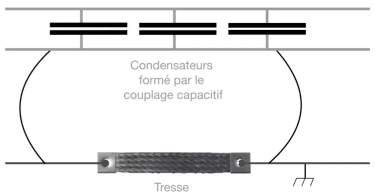
Capacitive coupling is present when two conductors run side by side.
ribs. They then form a planar capacitor together. You should know that a capacitor
the ability to store opposing electrical charges on its armatures. Note that a charge time is followed by a discharge time, and so on. These very rapid variations in current disturb the electrical system, and can induce an additional inductive coupling.
Realization on an installation
NB: the induced voltages are proportional to the size of the loops, with a constant of proportionality strictly greater than 1.
Earth
Land is essential to human security, in the face of malfunctions or surges such as lightning. This remains fully adapted to compatibility
electromagnetic and must be installed.
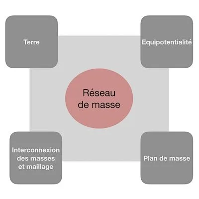
We finally arrive at the balance sheet diagram:
Realization and implementation
Depending on the electrical installation, electromagnetic compatibility is set up at
di ff erent levels.
Here is a diagram showing the di ff erent increasing levels of compliance with
electromagnetic compatibility.
- Installation of equipotential bonding between devices
electrical and priority conductive structures (gas, water, etc.) which meet at a central point. Of course with the presence of an earth electrode and an earth stake. - Installation of ground conductors allowing the inhibition of capacitive and inductive couplings. These ground conductors will be present between electrical devices and between priority conductive structures
- Using earth conductors, connect the secondary conductive structures (trunking, frame, frame, etc.) and the earth connection. All ground conductors will be connected to a main ground terminal.
- Installation of a large diameter mesh around the devices
electrical and conductive structures. It is possible to make a connection to the bottom of the excavation. - Installation of smaller and segmented meshes, to avoid the presence of magnetic fields. It is possible to install a conductive floor over the entire building. This last level makes it possible to protect equipment particularly sensitive to high energy surges such as lightning strikes.
GBM offers you solutions
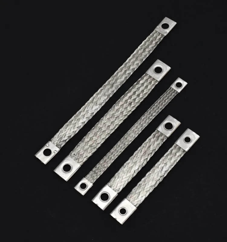
The ground braids can be used for earthing and equipotential connections. Due to their structures, they have a low linear inductance. It is therefore fully suitable for equipotential bonding and is very useful in ground conductor circuits.
The contact pads are made from annealed tubes crimped onto the braid and then punched to the diameter of the required screws.
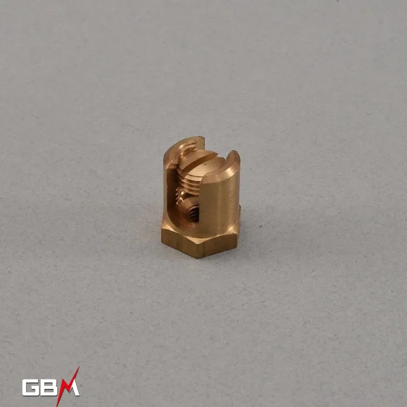
Brass terminals also called brass wire clamps are used on slab cable tray. They are used to fix the earth cable which ensures the earthing of the installation.
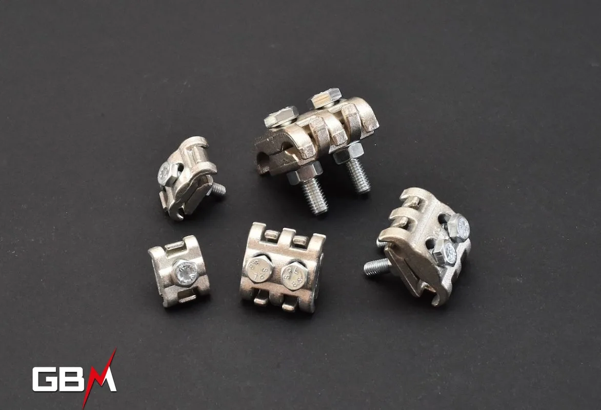
Tin-plated brass grips or “clamps” allow conductors to be connected to each other or can also be used to fix an earth wire or a ground braid on a wire cable tray.
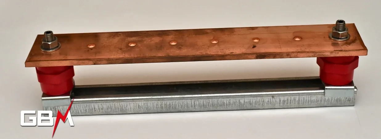
The equipotential bonding bar brings together the various earth circuits of an installation on the same support. The connections must be fixed using suitable screws to secure the connection.
For more information please contact us.

")